I have seen an interesting video connecting a J1772 (type 1) EV plug to an EV motorcycle [above]. Presumably there are some procedures to connect EU/UK IEC62196 (type 2) to road stations. Research is needed. A member of the Electric Motorcycle build page on FB posted a link that discuss the comms between charger/battery & roadside stations. The following text is directly from the site in case the site dies.
“The following article explains how the communication interface between a charging point and an electric vehicle is technically implemented in the Type 2 standard according to IEC 62196. Basic information on the type 2 connector system can be found under Charging and Charging Plugs.
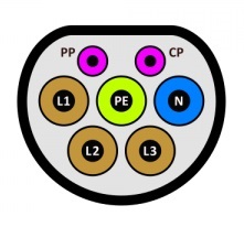
In addition to the five standard connections for three-phase current (PE, N, L1, L2, L3), a Type2 connector has two smaller contact pins: the control/data line CP (Control Pilot) and the charging cable detection contact PP (Proximity Pilot/Plug present).
CP – Control pilot: post-insertion signalling
PP – Proximity pilot: pre-insertion signalling
PE – Protective earth: full-current protective earthing system—6-millimetre (0.24 in) diameter
N – Neutral: single-/three-phase AC / DC-mid
L1 – Line 1: single-/three-phase AC / DC-midL2 – Line 2: three-phase AC / DC-mid
L3 – Line 3: three-phase AC / DC-mid
CP contact: communication line
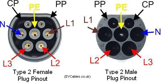
Pinouts for Type 2 male and female electric vehicle charging plugs
The charging station uses the data line CP to inform the electric car of the maximum charging current available. A square wave signal with a frequency of 1 kHz is used for this, which oscillates between +12 V and −12 V (with respect to the protective conductor). The pulse width (the duty cycle ) of the square-wave signal indicates the current intensity that can be taken. For a current between 6A and 48 A, the following formula applies:
- Available current (in A) = duty cycle (in%) · 0.6 A
respectively.
- Duty cycle (in%) = available current (in A) ÷ 0.6 A
Here are a few examples:
- Pulse width 50% → charging current max. 30 A
- Pulse width 27% → charging current max. 16 A
- Pulse width 16% → charging current max. 10 A
In order: First of all, no electric car is connected to the charging station and the type 2 socket is disconnected from the charging station (ie N, L1, L2 and L3 are interrupted). The rectangular signal of the charging station is still deactivated at this time, instead a voltage of +12 V is permanently applied to the CP via the 1 kΩ resistor.
If an electric car is now connected, this connects the CP line to the protective conductor via a diode and a 2.7 kΩ resistor. This pulls the voltage at CP from +12 V to +9 V (principle of voltage divider). Since the charging station measures the voltage at CP, it can now recognize that an electric car is connected. It then activates the square-wave signal with a pulse width corresponding to the available charging current. Thanks to the 1 kΩ resistor in the charging box, the diode and the 2.7 kΩ resistor in the electric car, the square wave signal on the CP oscillates between +9 V and −12 V.
The electric car measures the pulse rate of the signal and thus learns how much charging current is available to it. Incidentally, what it does not know is whether single-phase or three-phase charging is possible, because this does not play a role in the communication protocol. For example, if the pulse width indicates 16 A, it could mean a charging power of 3.7 kW single-phase or 11 kW three-phase.
When the electric car is ready to charge, it notifies the charging station by switching another resistor (value 1.3 kΩ) between the diode and the protective conductor. This pulls the upper voltage of the square wave signal from +9 V to +6 V. Since the charging station measures the voltage at CP, it now recognizes that the electric car wants to charge! So she switches on the power supply to the electric car via a contactor (i.e.N, L1, L2 and L3) and this charges his battery – at maximum with the current that the charging station specifies. Only now can the car also measure whether it is a single-phase or three-phase power connection.
During the entire charging process, the square-wave signal of the charging station continues to run (and fluctuates between +6 V and −12 V ). In the meantime, the charging station can change the pulse width, whereupon the electric car has to adjust its charging current accordingly. If the square signal breaks off completely, the electric car must stop charging immediately.
Once the electric car has fully charged (or the driver stops charging), it deactivates the 1.3 kΩ resistor, causing the upper limit voltage of the square wave signal to drop to +9 V. The charging station then switches off the power supply to the electric car and the Type 2 socket is voltage-free again.
PP contact: charging cable coding
Via the PP contact, both the charging station and the electric car can see how much the connected charging cable can be subjected to. For this purpose, a fixed resistor between PP and the protective conductor is installed in both Type 2 plugs, the value of which indicates the cross-section of the cables of the charging cable. The following resistance values are possible:
- resistance: 1.5 kΩ / Wire Gauge: 1.5 mm² / Max. charging current: 13A
- resistance: 680 Ω / Wire Gauge: 2.5 mm² / Max. charging current: 20A
- resistance: 220 Ω / Wire Gauge: 4-6 mm² / Max. charging current: 32A
- resistance: 100 Ω / Wire Gauge: 10-16 mm² / Max. charging current: 63A
Depending on the measured resistance, the charging station may reduce the pulse width of the square-wave signal. The electric car can also adjust its charging current.


One Comment Add yours