Have been looking at the spec for the kelly controller to find user manual for wiring diagrams etc. Seems to have been designed for QS MOTORS but an adapted version of the Kelly KLS7275: https://www.kellycontrollers.eu/kls7275h
Spec and details below:
- GENERAL SPECIFICATION
•Frequency of Operation: 20kHz.
•Standby Battery Current: < 0.5mA.
•5V or 12V Sensor Supply Current: 40mA.
•Controller supply voltage range: PWR, 18V to 90V for controllers rated equal or lower than 72V.
•Supply Current, PWR, 30mA Typical.
•Configurable battery voltage range, B+. Max operating range: 18V to 1.25*Nominal Voltage.
•Standard Throttle Input: 0-5 Volts (3-wire resistive pot), 1-4 Volts(hall active throttle).
•Throttle Input: 0-5 Volts. Can use 3-wire pot to produce 0-5V signal.
•Main Contactor Coil Driver <2A.
•Full Power Operating Temperature Range: 0℃ to 70℃ (MOSFET temperature).
•Operating Temper ature Range: -40℃to 100℃ (MOSFET temperature).
•Motor Current Limit, 20 seconds boost: 500A ,depending on the model.
•Motor Current Limit, continuous: 200A ,depending on the model.
•Max Battery Current :Configurable. - FEATURES
1) Intelligence with powerful microprocessor.
2) Synchronous rectification, ultra low drop, fast SVPWM and FOC to achieve very high efficiency.
3) Electronic reversing.
4) Voltage monitoring on 3 motor phases, bus, and power supply.
5) Voltage monitoring on voltage source 12V and 5V.
6) Current sense on all 3 motor phases.
7) Current control loop.
8) Hardware over current protection.
9) Hardware over voltage protection.
10) Configurable limit for motor current and battery current.
11) Low EMC.
12) LED fault code.
13) Battery protection: current cutback, warning and shutdown at configurable high and low battery voltage.
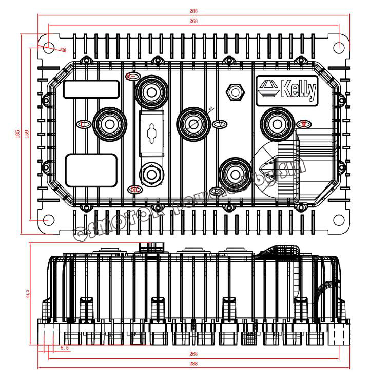
14) Rugged aluminium housing for maximum heat dissipation and harsh environment.
15) Rugged high current terminals, and rugged aviation connectors for small signal.
16) Thermal protection: current cut back, warning and shutdown on high temperature.
17) Configurable 60 degree or 120 degree hall position sensors.Controller can do auto_Identification angle for different degrees of hall sensors.
18) Configurable high pedal protection: the controller will not work if high throttle is detected at power on.
19) Current multiplication: Take less current from battery, output more current to motor.
20) Easy installation: 3-wire potentiometer will work.
21) Standard PC/Laptop computer to do programming.There is one more choice for customers to program KLS controller.Standard Tablet with Android OS to do programming.Need a Z-TEK USB TO RS232 cable for connecting the controller to App program in Tablet.
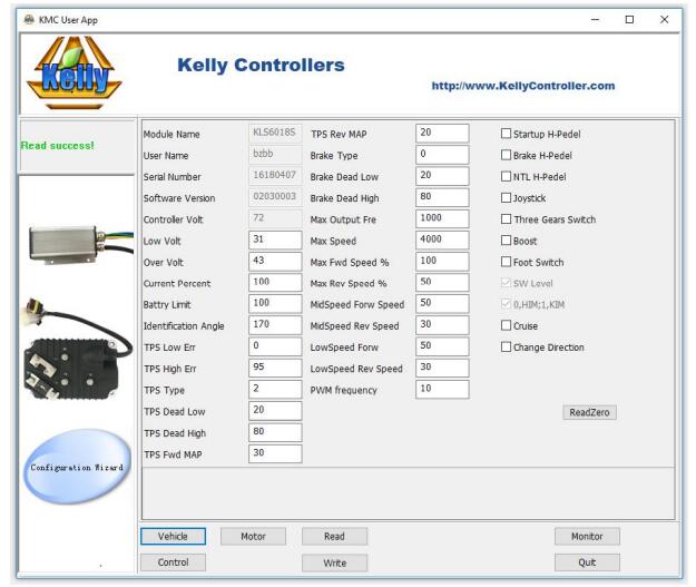
22) User program provided. Easy to use. No cost to customers.
23) Support motors with any number of poles.
24) Up to 70,000 electric RPM standard. (Electric RPM = mechanical RPM * motor pole pairs;Motor pole pairs=Motor poles/2). - GENERAL FUNCTIONS
(1)Extended fault detection and protection. The LED flashing pattern indicates the fault sources.Customers can read the error code in PC software or Android Tablet also.
(2)Monitoring battery voltage. It will stop driving if the battery voltage is too high and it will progressively cut back motor drive power as battery voltage drops until it cuts out altogether at the preset “Low Battery Voltage” setting.
(3)Built-in current loop and over current protection.
(4)Configurable motor temperature protection range.
(5)Current cutback at low temperature and high temperature to protect battery and controller. The current begins to ramp down at 90℃ case temperature, shutting down at 100℃.
(6)The controller keeps monitoring battery recharging voltage during regen braking.
(7)Maximum reverse speed and forward speed can be configured between 20% and 100% respectively and separately.
(8)A 4pin connector to RS232 port and a Z-TEK USB to RS232 cable allows for configuration, programming and software upgrades using the tablet which must be based on Android OS now.People can do the same things on PC software by using a standard USB to RS232 cable instead.
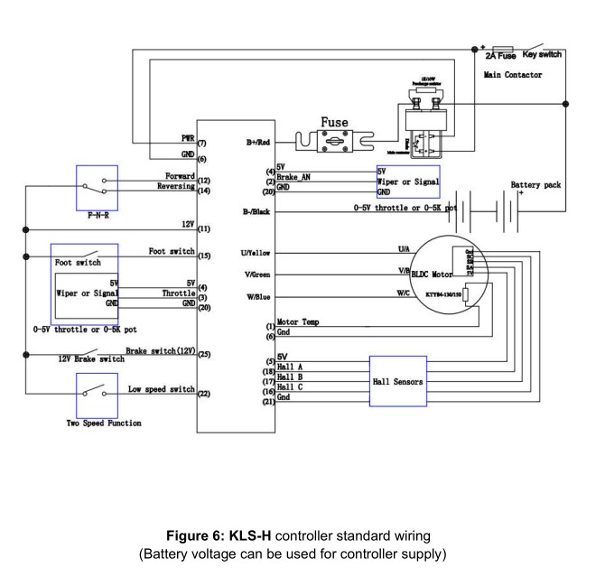
(9)Provision of a +5 volt and +12 volt output to supply various kinds of hall sensors.
(10)5 switch inputs which are activated by connection to 12V. Default to throttle switch, brake switch,reversing switch,forward switch and Boost switch.
(11)2 analog 0-5V inputs that default to throttle input, and motor temperature input
(12)Copy signal of one of hall sensors.
(13)Configurable boost switch. Enables the maximum output power achievable if the switch is turned on.
(14)12V brake switch input used different port from motor temperature sensor.You can use both brake switch and motor temperature sensor functions at the same time on the latest version.Pin 25 is 12V brake switch input port.Pin1 is motor temperature sensor input port.
(15)Optional joystick throttle. A bi-symmetrical 0-5V signal for both forward and reversing.
(16)Configurable motor over-temperature detection and protection with the recommended thermistor KTY84-130 or KTY84-150.
(17)3 hall position sensor inputs. Open collector, pull up provided.
(18) Brake analog regen mode.This regen mode doesn’t need brake switch to support any more.Only available from software version 0106.KLS controller can not support reflashing.
(19)Enhanced regen brake function. A novel ABS technique provides powerful and smooth regen.The regen can happen at any speeds until zero speed.
(20) KLS-H controller included the fuse on the case.Not shunt is attached.
(21) Cruise control.Only can be activated in forward direction.
(22) KLS-H can support Broadcast type CAN Bus function.It is 250Kbps.CAN bus is not
included in KLS-H controller by default.CAN bus is only an optional function for KLS-H.
CAN ID can be changed in the latest user program also.
PIN DEFINITION
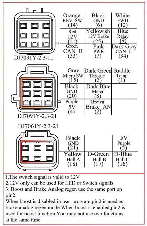
1. The switch signal is valid to 12V on pin11
2. 12V capacity is low.This 12V only can be used for LED or switch signals.
3. Boost and Brake analog regeneration mode used the same pin as pin2. When Boost is disabled in the user program, the pin2 can be used as brake variable regen mode.When Boost is enabled,the brake analog regen mode is inactivated automatically.Both Boost and Brake variable regen mode can not be used at the same time. 3.Boost and Brake analog regeneration mode used the same pin as pin2. When Boost is disabled in the user program, the pin2 can be used as brake variable regen mode.When Boost is enabled,the brake analog regen mode is inactivated automatically.Both Boost and Brake variable regen mode can not be used at the same time.
DJ7091Y-2.3-11 Pin Definition
(14) REV_SW: Reverse switch input. Orange
(6) RTN: Signal return or power supply return. Black
(12) FWD: Forward switch or High speed switch White
(11) 12V:12V Source Red
(22) ECO: Low speed switch input. Blue
(7) PWR: Controller power supply (input). Pink
(25) 12V brake switch . Yellow
DJ7091Y-2.3-21 Pin Definition
(15) Micro_SW: Throttle switch input. Gray
(3) Throttle: Throttle analog input, 0-5V. Green
(1) Temp: Motor temperature sensor input. Raddle.
(20) RTN: Signal return. Black
(8) Meter: Copy signal of hall sensors. Dark Gray
(4) 5V: 5V supply output, <40mA. Purple
(2) Brake_AN :Brake variable regen or Boost function. Brown
DJ7061Y-2.3-21 Pin Definition
(21) RTN:Signal return. Black
(5) 5V: 5V supply output,<40mA.Purple
(18) Hall A: Hall phase A. Yellow
(17) Hall B: Hall phase B. Dark Green
(16) Hall C: Hall phase C. Dark Blu
NOTES
– All RTN pins are internally connected.
– Meter function is to copy either of hall sensors.
– Switch to 12V is active.
– Open switch is inactive.